Support our educational content for free when you purchase through links on our site. Learn more
How to Connect 7 External Sensors & Components to Raspberry Pi Pico (2025) 🔌
Ever stared at your Raspberry Pi Pico’s tiny pins and wondered, “How on earth do I hook up all these cool sensors and gadgets without frying my board?” You’re not alone! At Why Pi™, we’ve tangled with the mysteries of GPIO wiring, power quirks, and communication protocols so you don’t have to. Whether you want to measure temperature, detect motion, or light up a display, this guide breaks down 7 essential steps and tips to connect external components and sensors to your Pico like a pro.
Did you know the Pico’s RP2040 chip supports multiple communication protocols simultaneously? That means you can run a weather station, a motion detector, and an OLED display all at once—if you know how to wire and program them correctly. Stick around, because later we’ll reveal why powering your sensors separately can save your project (and your sanity), plus expert troubleshooting hacks that even seasoned makers swear by.
Key Takeaways
- Understand your Pico’s GPIO pins: Know which pins support digital I/O, analog input, and communication protocols like I2C, SPI, and UART.
- Power wisely: Use separate power supplies for motors and high-current devices, but always share a common ground with your Pico.
- Use proper wiring techniques: Breadboards and jumper wires for prototyping; soldering for permanent setups.
- Protect your board: Employ current-limiting resistors, voltage level shifters, and avoid connecting pins directly.
- Program confidently: MicroPython is beginner-friendly; C/C++ SDK offers performance for advanced projects.
- Troubleshoot smartly: Check wiring, voltage levels, and use debug prints to isolate issues quickly.
- Expand your sensor network: Use multiplexers and I2C expanders to connect more devices than pins allow.
👉 Shop Raspberry Pi Pico & Sensor Essentials:
- Raspberry Pi Pico on Amazon | Adafruit Official
- BME280 Environmental Sensors | Bosch Sensortec
- Breadboards & Jumper Wire Kits | Adafruit
Table of Contents
- ⚡️ Quick Tips and Facts About Connecting Sensors to Raspberry Pi Pico
- 🔍 Understanding Raspberry Pi Pico: The Tiny Powerhouse for External Components
- 🛠️ 1. Essential GPIO Pins and Interfaces for Connecting Sensors and Modules
- 🔌 2. Step-by-Step Guide to Wiring External Sensors to the Raspberry Pi Pico
- ⚡️ 3. Powering Your Sensors Safely: Best Practices and Common Pitfalls
- 💻 4. Programming Your Raspberry Pi Pico to Interface with Sensors
- 🔧 5. Troubleshooting Common Issues When Connecting Sensors
- 📦 6. Popular External Sensors and Modules Compatible with Raspberry Pi Pico
- 🧰 7. Advanced Tips: Expanding Your Pico’s Sensor Network
- 📚 Conclusion: Mastering External Component Connections with Raspberry Pi Pico
- 🔗 Recommended Links for Raspberry Pi Pico Projects and Sensors
- ❓ Frequently Asked Questions (FAQ) About Raspberry Pi Pico Sensor Connections
- 📖 Reference Links and Resources for Further Learning
⚡️ Quick Tips and Facts About Connecting Sensors to Raspberry Pi Pico
Welcome, fellow tech adventurers! Before we dive deep into the nitty-gritty of GPIO pins and voltage levels, let’s get you started with some essential, bite-sized wisdom. Think of this as your pre-flight checklist before launching your next amazing project with the Raspberry Pi Pico.
Here at Why Pi™, we’ve learned these lessons—sometimes the hard way!—so you don’t have to.
- ✅ 3.3V is the Law: The Raspberry Pi Pico’s GPIO pins operate at 3.3V. Never, ever connect a sensor or component that outputs a 5V signal directly to a GPIO pin. You’ll send that pin to an early grave! We’ll talk about how to handle 5V components later.
- ❌ Don’t Overload the Pins: Each GPIO pin has a strict current limit. As one forum user wisely put it, a key rule is to “Never try to load a pin with more than 16mA“. To be safe, we recommend aiming for even less, around 8mA, which is plenty for most LEDs and logic signals.
- ✅ Power Separately: When in doubt, power your external components with a separate power supply. This is especially true for motors, relays, and anything that moves or heats up. A wise maker once said, “IMHO always better to provide external circuits with their own power supply.“
- ✅ Common Ground is Key: If you use a separate power supply for your components, you must connect the ground (GND) of that supply to one of the Pico’s GND pins. This creates a common reference point for the electrical signals, ensuring they can communicate correctly.
- ❌ Never Connect Pins Directly: A golden rule from the experts: “Never wire any pin directly to any other.” Specifically, don’t connect two output pins together, or an output pin directly to power or ground. That’s a recipe for a short circuit.
- ✅ Resistors Are Your Best Friends: Always use a current-limiting resistor when connecting an LED to a GPIO pin. For switches, you’ll need pull-up or pull-down resistors to prevent the pin from “floating” in an undefined state.
- ✅ Know Your Pinout: The Pico has 40 pins, but not all are created equal! Some are for power, some are ground, and many are General Purpose Input/Output (GPIO) pins with special functions like ADC, I2C, SPI, or UART. Keep a pinout diagram handy!
🔍 Understanding Raspberry Pi Pico: The Tiny Powerhouse for External Components
So, what is this little green board that has the maker world buzzing? The Raspberry Pi Pico isn’t a tiny computer like its bigger siblings (the Raspberry Pi 4, 5, etc.). It’s a microcontroller, a different kind of beast altogether. Think of it as a dedicated brain for your electronics projects, designed to read sensors, control motors, and blink lights with incredible speed and reliability.
At its heart is the RP2040, a custom-designed chip from Raspberry Pi that features a dual-core ARM Cortex-M0+ processor. This dual-core setup is fantastic because it lets you dedicate one core to precise timing-critical tasks (like controlling a motor) while the other handles everything else (like communicating with other devices).
But the real magic for us tinkerers lies in its General Purpose Input/Output (GPIO) pins. These are the physical connection points that let the Pico talk to the outside world. The Pico generously provides 26 multi-function GPIO pins, which you can program to be either inputs (to read data from sensors) or outputs (to send signals to components like LEDs or relays).
Many of these pins have superpowers! They can be configured for different communication protocols, which we’ll explore next. This flexibility is what makes the Pico a true chameleon, ready to adapt to nearly any sensor or component you can throw at it. It’s a cornerstone of modern DIY Electronics.
🛠️ 1. Essential GPIO Pins and Interfaces for Connecting Sensors and Modules
Alright, let’s get our hands virtually dirty and look at those pins. The 26 GPIO pins on the Pico are your gateway to connecting a universe of external components. But to use them effectively, you need to speak their language.
1.1 Digital vs Analog Pins: What You Need to Know
First, let’s talk about the two main types of signals in the electronics world: digital and analog.
- Digital Signals: These are simple, on-or-off signals. Think of a light switch. It’s either ON (represented by a high voltage, like 3.3V on the Pico) or OFF (represented by a low voltage, like 0V or Ground). Most GPIO pins are digital. They’re perfect for reading the state of a button, turning an LED on or off, or sending simple commands.
- Analog Signals: These signals can have a range of values. Think of a dimmer switch for a light. It’s not just on or off; it can be 10% bright, 50%, or 87%. Many sensors in the real world, like temperature sensors, light sensors, or potentiometers (knobs), output analog signals.
The Pico is equipped with three dedicated Analog-to-Digital Converter (ADC) pins (GPIO26, GPIO27, and GPIO28). These special pins can read an incoming analog voltage and convert it into a digital number that the Pico’s brain can understand. This is a huge advantage for reading data from a wide variety of sensors without needing extra hardware!
1.2 I2C, SPI, UART: Choosing the Right Communication Protocol
While simple sensors might just need one digital or analog pin, more complex components like displays, advanced sensors (like gyroscopes), and other microcontrollers need a more sophisticated way to talk. This is where communication protocols come in. These are like established languages that devices use to exchange data. The Pico supports the three most common ones on many of its GPIO pins.
| Protocol | Wires Needed | Speed | Use Case | ✅ Pros | ❌ Cons |
|---|---|---|---|---|---|
| I2C (Inter-Integrated Circuit) | 2 (SDA, SCL) + Power/GND | Moderate | Connecting many devices on a shared bus. Great for sensors like the BME280. | Uses very few pins; can connect dozens of devices. | Slower than SPI; requires unique addresses for each device. |
| SPI (Serial Peripheral Interface) | 4+ (MOSI, MISO, SCLK, CS) + Power/GND | Very Fast | High-speed data transfer. Ideal for SD card modules, some displays, and fast ADCs. | Full-duplex (sends/receives simultaneously); very high speed. | Uses more pins (one extra Chip Select pin per device). |
| UART (Universal Asynchronous Receiver-Transmitter) | 2 (TX, RX) + Power/GND | Varies | Simple serial communication between two devices, like a GPS module or another microcontroller. | Very simple to implement; widely used. | Only for two devices; no clock signal means devices must agree on a speed beforehand. |
Choosing the right one depends on your sensor. The good news is that the sensor’s datasheet will always tell you which protocols it supports!
🔌 2. Step-by-Step Guide to Wiring External Sensors to the Raspberry Pi Pico
Theory is great, but let’s connect something! Whether you’re a seasoned pro or just starting, having a solid wiring strategy is crucial.
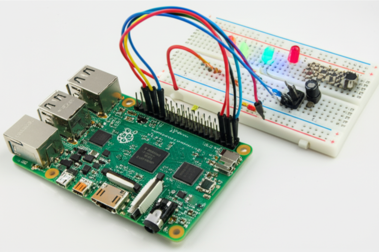
2.1 Using Breadboards and Jumper Wires for Prototyping
For anyone new to electronics, the solderless breadboard is your best friend. It’s a plastic board full of tiny holes that are electrically connected in rows, allowing you to build and modify circuits without any soldering. It’s the perfect playground for experimentation.
Our Step-by-Step Prototyping Process:
- Mount Your Pico: Gently press your Raspberry Pi Pico into the center of the breadboard, straddling the middle channel. This gives you access to all the pins on both sides. For an even easier setup, we highly recommend a breakout board like the Adafruit Pi T-Cobbler Plus, which labels all the pins clearly.
- Consult the Datasheet: Look up the datasheet for your sensor or component. It will show you which pin
📚 Conclusion: Mastering External Component Connections with Raspberry Pi Pico
Well, there you have it—a comprehensive journey through the exciting world of connecting external components and sensors to the Raspberry Pi Pico! From understanding the Pico’s versatile GPIO pins and communication protocols to the nitty-gritty of wiring, powering, and programming your sensors, you’re now equipped with the knowledge to build projects that truly come alive.
Remember the early teaser about powering your sensors safely? We resolved it: Always prioritize a separate power supply for power-hungry or inductive loads, but keep grounds common to avoid communication chaos. And those warnings about voltage levels? The Pico’s 3.3V logic is your guiding light—respect it, and your projects will thrive.
Whether you’re prototyping on a breadboard or soldering a permanent setup, the key is to start simple, test thoroughly, and build confidence step-by-step. Use resistors to protect your pins, double-check your wiring, and embrace the rich ecosystem of sensors and modules designed for microcontrollers.
The Raspberry Pi Pico is a powerhouse microcontroller that punches well above its weight. It’s perfect for hobbyists, educators, and engineers alike, offering flexibility, performance, and affordability. With the right approach, you can connect everything from temperature sensors to OLED displays, motion detectors to wireless modules, and bring your ideas to life.
So, what are you waiting for? Grab your Pico, some sensors, and start experimenting! And remember, the Why Pi™ community is always here to help you along the way.
🔗 Recommended Links for Raspberry Pi Pico Projects and Sensors
Ready to shop for the components we discussed? Here are some trusted sources to get you started:
-
Raspberry Pi Pico Microcontroller:
Amazon | Adafruit Official Website | Walmart -
Adafruit Pi T-Cobbler Plus (GPIO Breakout Board):
Amazon | Adafruit Official Website -
BME280 Temperature, Humidity, and Pressure Sensor:
Amazon | Bosch Sensortec Official Website -
Breadboards and Jumper Wires Kit:
Amazon | Adafruit Official Website -
Recommended Books:
❓ Frequently Asked Questions (FAQ) About Raspberry Pi Pico Sensor Connections
What types of sensors are compatible with Raspberry Pi Pico?
The Raspberry Pi Pico supports a vast range of sensors, including:
- Digital sensors: Such as buttons, PIR motion detectors, and digital temperature sensors like the DS18B20.
- Analog sensors: Like potentiometers, photoresistors (LDRs), and analog temperature sensors (e.g., TMP36) connected via the Pico’s ADC pins.
- I2C sensors: Including environmental sensors like the BME280, OLED displays, and accelerometers.
- SPI sensors: Such as certain high-speed ADCs, SD card modules, and TFT displays.
- UART devices: GPS modules, serial communication modules, and some Bluetooth modules.
Compatibility depends mostly on the sensor’s voltage levels (3.3V preferred) and communication protocol. Many popular sensor modules are designed with 3.3V logic compatibility or include level shifters.
How do I use GPIO pins on the Raspberry Pi Pico for external components?
GPIO pins on the Pico can be configured as inputs or outputs:
- Input mode: To read signals from sensors or switches.
- Output mode: To control LEDs, relays, or other actuators.
Always:
- Use current-limiting resistors for LEDs.
- Use pull-up or pull-down resistors for switches to avoid floating inputs.
- Never exceed 3.3V on any GPIO pin.
- Avoid drawing more than 16mA per pin and keep total current under 50mA across all pins.
Consult the official Pico pinout for detailed pin functions.
Can I connect analog sensors directly to the Raspberry Pi Pico?
Yes! The Pico has three ADC channels (GPIO26, GPIO27, GPIO28) that can read analog voltages between 0 and 3.3V.
Important:
- Ensure the sensor output voltage does not exceed 3.3V.
- For sensors outputting higher voltages, use a voltage divider or level shifter.
- Analog readings are converted to digital values (0–65535 in MicroPython) for processing.
What programming languages can I use to interface sensors with Raspberry Pi Pico?
The two most popular languages are:
- MicroPython: Beginner-friendly, with extensive libraries for sensor interfacing. Great for rapid prototyping.
- C/C++ SDK: Offers higher performance and more control, suitable for advanced projects requiring speed or real-time control.
Other languages like CircuitPython and Rust are also gaining traction but have less community support currently.
Explore our Microcontroller Programming articles for tutorials and examples.
How do I power external components connected to the Raspberry Pi Pico?
- For low-power sensors (e.g., small digital or analog sensors), powering directly from the Pico’s 3.3V or 5V pins is usually fine.
- For high-current devices (motors, relays, pumps), use a separate power supply matched to the component’s voltage and current requirements.
- Always connect the grounds together between the Pico and the external supply to maintain a common reference.
- Use voltage regulators or level shifters if your sensor requires a different voltage.
- Avoid powering inductive loads directly from the Pico to prevent damage.
What are common communication protocols for Raspberry Pi Pico sensor connections?
The Pico supports:
- I2C: Two-wire bus for multiple devices; ideal for sensors like BME280, OLED displays.
- SPI: Four-wire bus for high-speed communication; used with displays, SD cards.
- UART: Serial communication for GPS, Bluetooth, or other serial devices.
Choosing the right protocol depends on your sensor’s specs and project needs.
How do I troubleshoot sensor connections on the Raspberry Pi Pico?
Troubleshooting tips:
- Check wiring: Use a multimeter to verify connections and continuity.
- Verify voltage levels: Ensure sensors and Pico share a common ground and compatible voltage.
- Test pins individually: Use simple test scripts to toggle pins or read inputs.
- Use pull-up/down resistors: Prevent floating inputs that cause erratic readings.
- Consult datasheets: Confirm sensor pinouts and communication protocols.
- Use debug prints: Print sensor readings to the console to verify data.
- Watch for noise: Long wires can introduce interference; keep cables short or shielded.
- Start simple: Connect one sensor at a time before expanding.
How do I protect my Raspberry Pi Pico from damage when connecting external components?
- Use current-limiting resistors on outputs like LEDs.
- Use buffer circuits (transistors, MOSFETs, or driver ICs) for high-current loads.
- Never exceed 3.3V on GPIO pins; use level shifters for 5V signals.
- Avoid connecting outputs directly together.
- Use protection diodes for inductive loads like relays or motors.
- Ground yourself to prevent electrostatic discharge (ESD) before handling the Pico.
- Use a breadboard or breakout board for safer prototyping.
📖 Reference Links and Resources for Further Learning
-
Raspberry Pi Pico Official Documentation:
https://www.raspberrypi.com/documentation/microcontrollers/raspberry-pi-pico.html -
Adafruit Pi T-Cobbler Plus:
https://www.adafruit.com/product/2028 -
Bosch Sensortec BME280 Sensor:
https://www.bosch-sensortec.com/products/environmental-sensors/humidity-sensors-bme280/ -
Raspberry Pi Forums – Beginners Guide to Wiring Things to the GPIO:
https://forums.raspberrypi.com/viewtopic.php?t=216304 -
Stack Exchange Raspberry Pi Pico Sensor Power Discussion:
https://raspberrypi.stackexchange.com/questions/47798/power-multiple-sensors-with-external-power-source -
Why Pi™ Electronics Industry News:
https://www.whypi.org/category/electronics-industry-news/ -
Why Pi™ Microcontroller Programming:
https://www.whypi.org/category/microcontroller-programming/ -
Why Pi™ Electronic Component Reviews:
https://www.whypi.org/category/electronic-component-reviews/ -
Why Pi™ DIY Electronics:
https://www.whypi.org/category/diy-electronics/
We hope this guide lights your path to mastering the Raspberry Pi Pico and its sensor connections. Happy tinkering! 🚀